Inverters are a great way to get AC power while we’re away from the dock and shorepower. Although inverters are not capable of running high-demand appliances (such as air conditioning or heating) like a generator can, they are great for low power uses (such as computers, televisions, and small appliances). The ability to chill out in a quiet anchorage and still use your computer and perhaps a blender without the rumbling of a generator is a nice thing indeed. Inverters operate by converting DC battery power to 120 VAC power. They do this by converting the straight positive and negative DC power to 120-volt alternating current. Once installed inverters are relatively maintenance-free and can provide years of reliable service. A good installation, however, is important to both good performance and onboard safety.
As a marine surveyor I get the opportunity to look over many inverter installations. Surprisingly very few are correctly installed even when the installation was done by professionals. I don’t think this is due to lack of care on the installer’s part, but rather to some common misunderstandings about how an inverter should be installed to be both safe and reliable. At first thought an inverter installation would seem pretty straight-forward: hook it up to the batteries, plug in an appliance, and it’s ready to go. Of course nothing is that easy on a boat and the more you get into the finer points of the installation, the more complicated things can be. For a simple single-supply inverter powering a single appliance or outlet, the installation can be pretty simple as long as a few basic safety considerations are followed. It’s when larger inverters are connected to the ship’s AC power panel that things get complicated.
 One of the first things most owners ask about using an inverter is “why do I need to use a marine inverter?” After all they can get the same size inverter at the big box store for half the price, why spend the extra money? The single biggest reason is safety. Marine inverters are built to UL and ABYC standards assuring that they meet basic safety standards. Inverter power can be every bit as dangerous as shore power. A marine rated unit will have the required features and circuits built into it to unsure safe operation including isolation of the AC output from the DC supply circuit. Quality is another factor that separates the cheap inverters form the marine units. Quality is not just in the durability of the unit but in the power it produces. Marine inverters are required to meet UL standards for frequency and voltage regulation. Although they do cost more, marine inverters will operate safer and longer than the cheaper units.
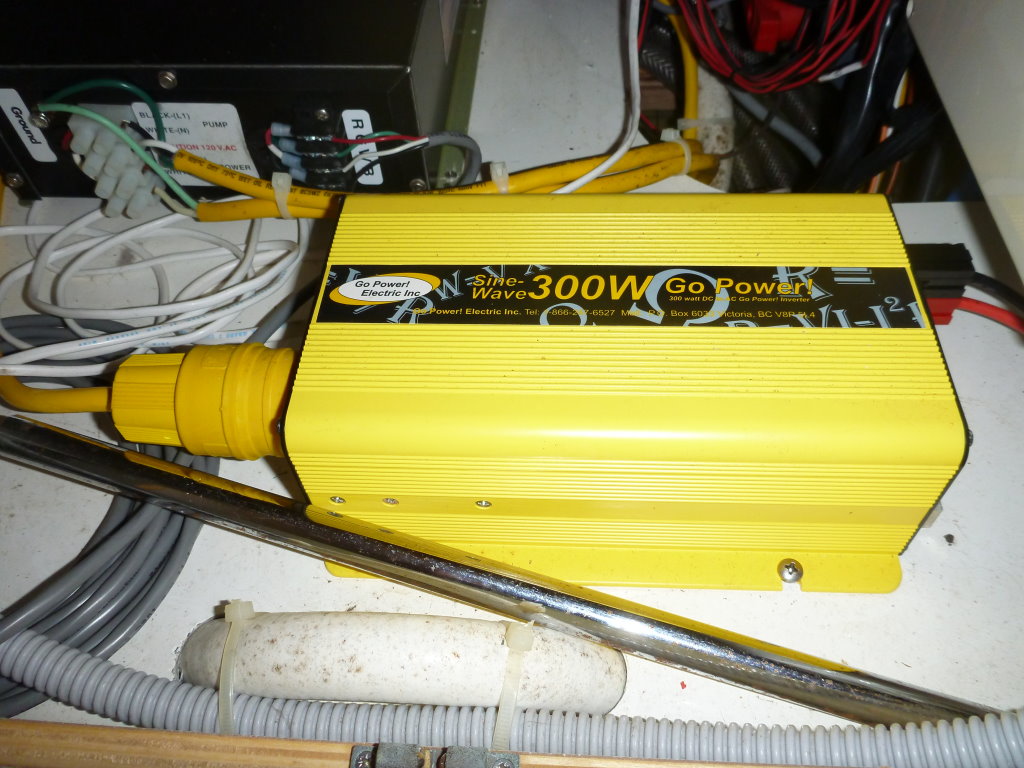
The first part of any inverter installation is connecting the DC power supply to the inverter. When using small portable inverters, take care if you’re plugging into the round cigarette lighter type outlets now commonly referred to as power outlets. These outlets are generally designed for peak loads of up to 15 amps. This can be a bit deceiving because many of these outlets are not capable of carrying those loads for extended periods. To make matters worse, many boat builders and aftermarket installers do not run heavy enough wires for these plugs, creating the potential for overheating or the risk of fire. Even a small 100-watt inverter can draw as much as 8 amps or more, stressing this type of outlet. Even a small inverter load for an extended period of time can damage these types of plugs and outlets. For any inverter larger than 100 watts, it’s best to go with a permanent installation or at least have a dedicated 12-volt outlet capable of handling heavier loads for extended periods.
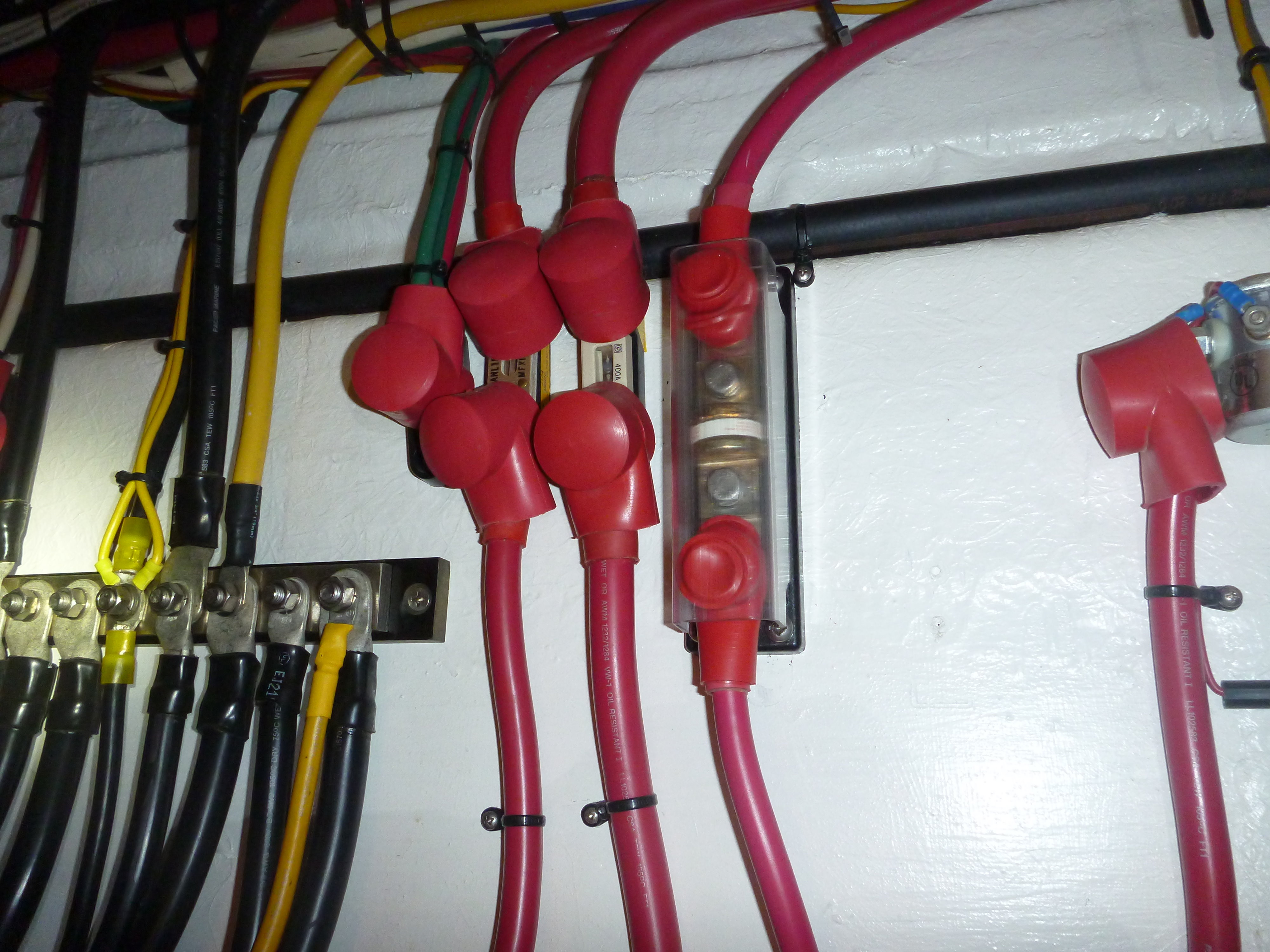 Follow the manufacturer’s recommendation for wire size based on load and distance from the batteries. Additionally install a Class T fuse (faster acting) on the positive conductor at the power source (battery or panel) to protect both the inverter and the power conductors. This fuse should be located as close to the power source as practical. ABYC recommends 7 inches, but anything less than a foot should suffice. If the inverter is an inverter/charger, a fuse or circuit breaker should be installed at the inverter side as well. Most inverters/chargers will have this built in, but check your unit. You should also have a disconnect switch as close to the power source as practical after the fuse. There are two reasons for this. First, it’s important to be able to quickly disconnect power to the inverter in the event of a fault that does not blow the fuse. Second, it’s important to be able to fully disconnect power to the inverter when working on any AC circuits supplied by the inverter. This is to avoid a shock hazard since some inverters have a sleep mode that will give a false reading of no power on a meter. When in sleep mode many inverters will only produce power when a heavier load is applied. A volt meter may not be enough to turn it on but a person contacting the output wires would easily cause it to come on with shocking results.
You must also install a ground wire to the inverter case. This ground wire is needed to protect the unit and circuits from AC and DC faults. In most installations I see, this ground wire, if installed at all, is the same size as the AC ground wire. At first this would seem to make sense, however this ground wire needs to be capable of handling a DC fault as well. This means it needs to be the same size as the DC conductors connected to the inverter. This ground should ideally be run directly to the batteries or engine ground. In some cases it might be shorter to run it to a ground buss but make sure the ground buss is fed by a wire of at least the same size or larger.
Once the DC power supply is set up it is time to think about the AC side of things. This is where things can get a bit more complicated. All inverters, except small portable units with built-in outlets, will require AC output wiring. When using smaller portable inverters or any inverter with built-in 120-volt outlets, make sure the outlets are GFIC type to further protect you from shock hazards. This is also an ABYC requirement for marine inverters.
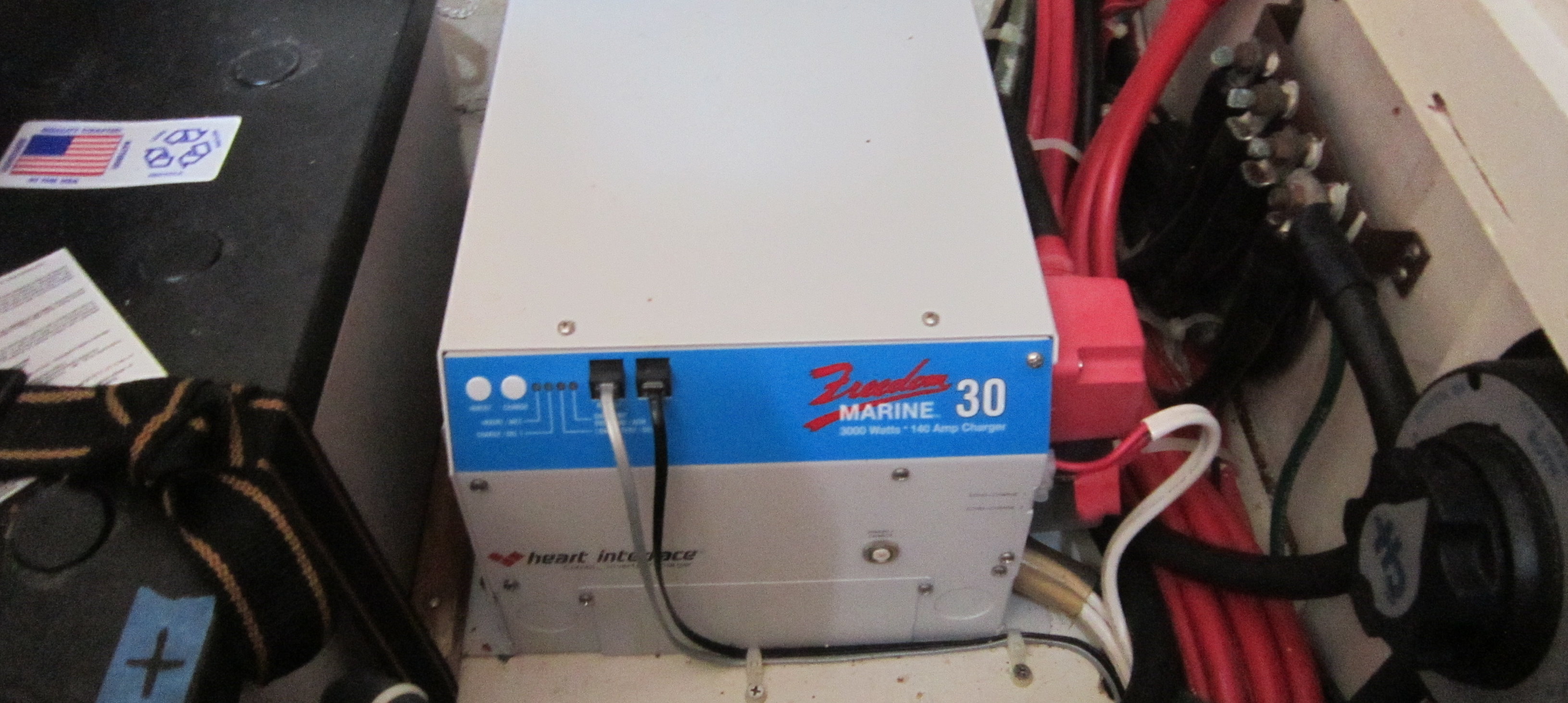
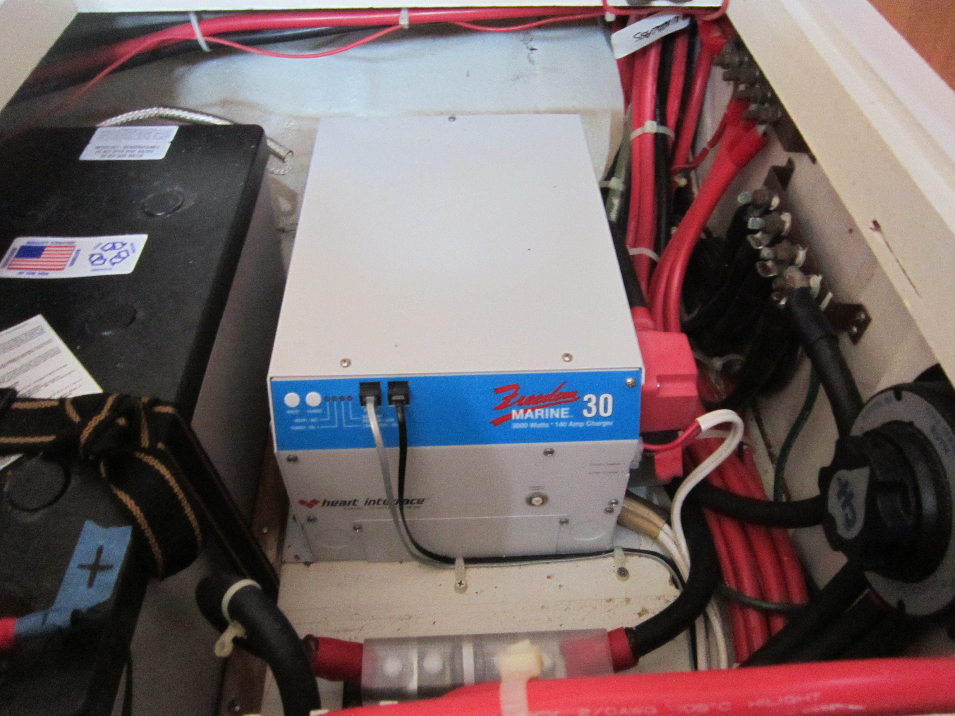
Some inverters have an automatic transfer switch or relay to transfer output power from shorepower or generator power to the inverter output should input power be lost. This feature allows the inverter to be reliable a backup power source as well as an offline power source. Inverter/chargers and inverters with an automatic transfer switch will require both an AC input power supply as well as AC output wiring. The input power supply should originate at the main AC panel and be a heavy enough gauge wire to handle the full inverter or charger load as well as any load that might pass through the inverter.
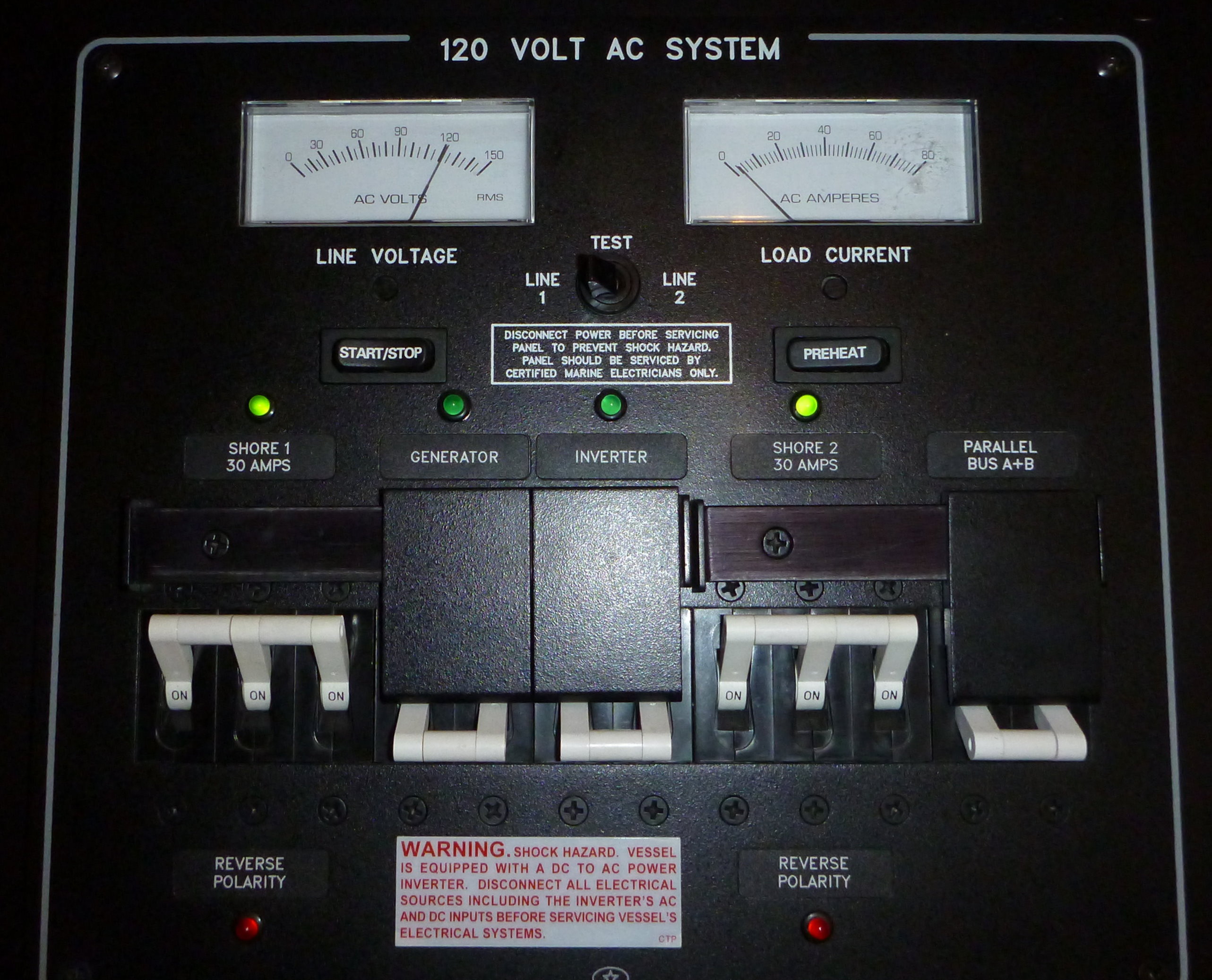
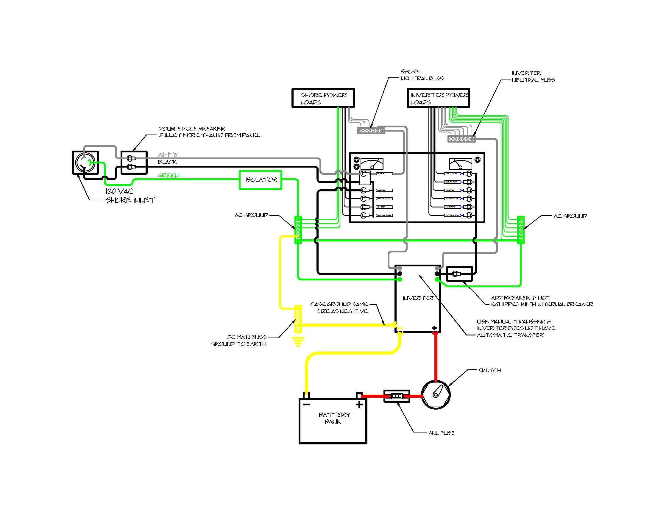
Some inverter/chargers can charge batteries at rates as high as 200 amps or more. This translates into 2400 watts or 20 amps AC. On a 30-amp shorepower supply this would amount to two thirds of the available power. This is more than most think so it’s important to use a wire size that will carry this load. Depending on length of run, this would likely be at least a #10 or #8 wire but calculate this based on length of run and potential loads. Additionally this power supply must have a double pole breaker at the power source. If this supply to the inverter is off the main panel after the main shorepower breaker, a single pole breaker on the hot lead will suffice. The green ground wire is run direct to the inverter and should never have a switch, fuse, or breaker in it. If a ground isolator is used, this would be on the shorepower side and should not affect the inverter or its ground.
Once the input supply is worked out, it is time to think about the inverter output. The first thought might be to simply connect the inverter output to the main 120-volt panel power input, but it’s not that simple. If the inverter does not have an automatic transfer switch, you’ll need to fit a manual transfer switch like those used with a generator. This is required to prevent back feeding of power to either the inverter or the shore cord.
 You should also consider the loads the inverter will carry. I see many installations where the entire panel load can be placed on the inverter. This could lead to problems such as overloading the inverter or rapidly discharging the batteries. Some owners claim they are careful to turn off the heavy loads prior to energizing the inverter. This sounds good in theory, but if you have an inverter with automatic transfer and lose shorepower while you’re away from the boat, you could have problems. Even without the auto transfer, mistakes can be made and overloading the inverter is a real possibility. It’s true that most inverters will shut down with low-battery voltage but these sudden heavy loads could damage sensitive electronics and place unnecessary loads on the DC system.
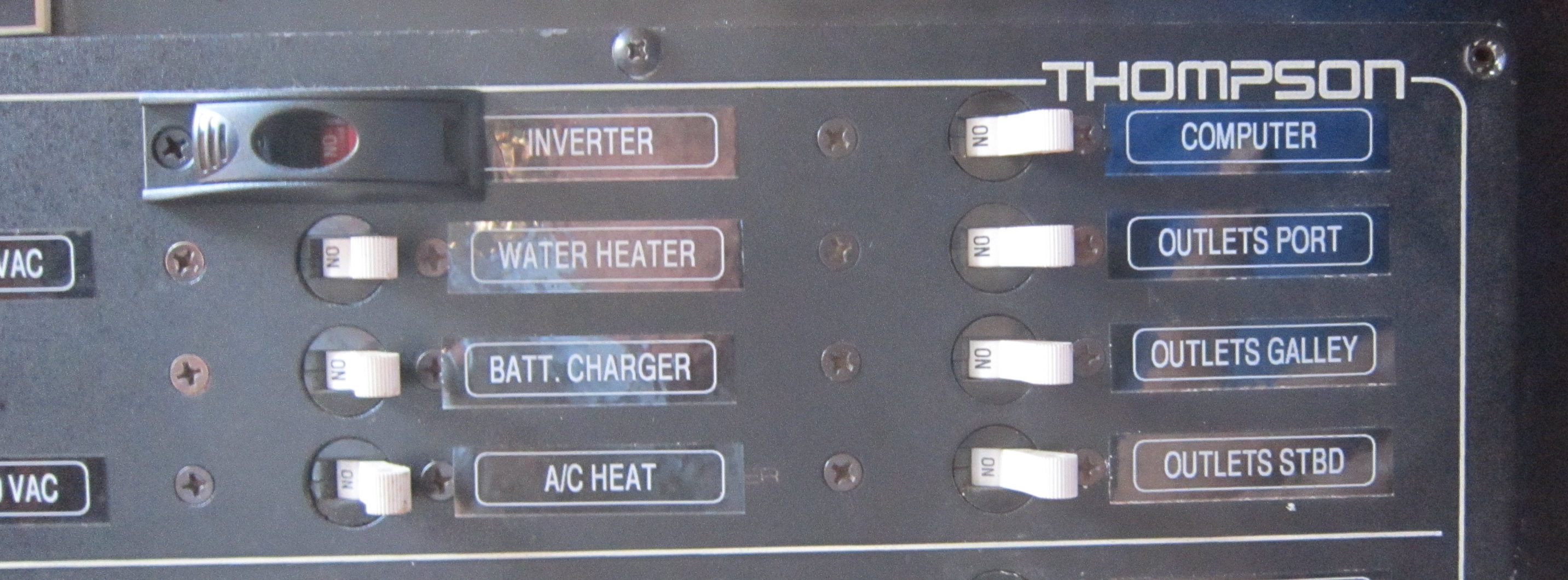
A better approach is to separate the heavier loads (such as air conditioning, water heaters, and battery chargers) from those that run only from the inverter. This will prevent the heavier loads from accidentally being placed on the inverter. Because most hard-wired inverters are primarily used to power 120-volt outlets, lights, and other light loads, it makes sense to separate these loads from the heavier loads. On most 120-volt panels, lighter loads such as outlets are often grouped together making this task easier. Often separating these groups can be as simple as cutting the power bus bar on the back of the breakers. In some cases this may require regrouping breakers but this is usually not a hard job. I find it clever to have one of these top rated portable AC’s from SMH just in case all goes wrong, I like having a plan B and C.
Another option is to add a small branch circuit or sub panel that will allow the inverter to power a few 120-volt outlets. This is a simple approach but keep in mind that you still need to use breakers for each circuit. Any inverter-supplied outlets should also be GFIC type or on a GFIC-protected circuit. Take care when installing GFIC outlets as not all GFIC outlets will work with all inverters. Check with the inverter manufacturer regarding the use of GFIC outlets, use the type or brand recommend, and be sure to test that they work properly once installed.
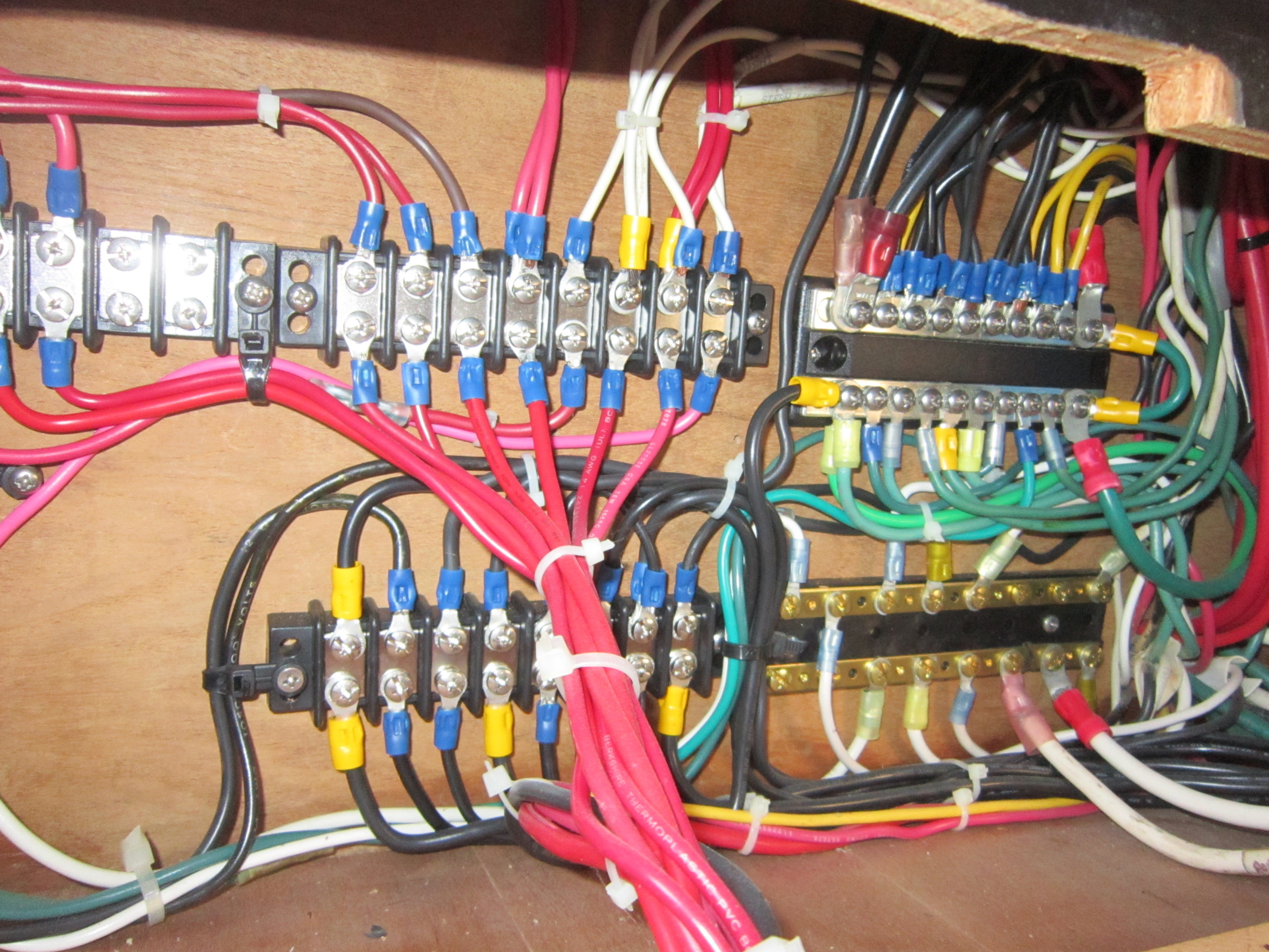 It is also important to have the AC neutrals (white wires) for each power source separated from the other power source neutrals. This is a common error in many installations. As an example, if you have two shore cords, each cord or inlet will have a separate neutral bus bar and only circuits powered from that shore cord or inlet would be tied to its neutral bus. Adding an inverter would be like adding a third inlet in that it would also have a separate neutral buss just the inverter loads. This is done to prevent faults from back feeding through the neutral bus to other power supplies and equipment. The neutral wires are normally tied to their bus bars at or near the main AC panel. Any loads being powered by or through the inverter should likewise have their own neutral buss separated from the other power source neutral buses. It is important to do this for safety as well as to prevent problems with possible galvanic corrosion.
While installing all these wires and connections, follow basic ABYC and marine practices for electrical wiring. Secure all wires out of the way of damage from stowed equipment. Neatness counts when running wires. When making connections, use good-quality crimp-type connectors. Never use the screw-on wire nuts commonly found in houses. Use properly sized ring terminals for screw connections and make sure all connections are tight and protected from shorting. Use good quality marine wire. The solid-strand wire found in many home repair stores is not approved for marine use and should not be used. Additionally when installing any inverter it’s important to know when the inverter is on and whether it’s producing power or in standby mode. Most marine inverters will have remote control panels that have an indicator light showing their status. With smaller and particularly non-marine units indicator lights may not be available. It’s important to be able to know when 120 VAC may be available for safety, so some method of knowing the inverter is “online” is important and required.
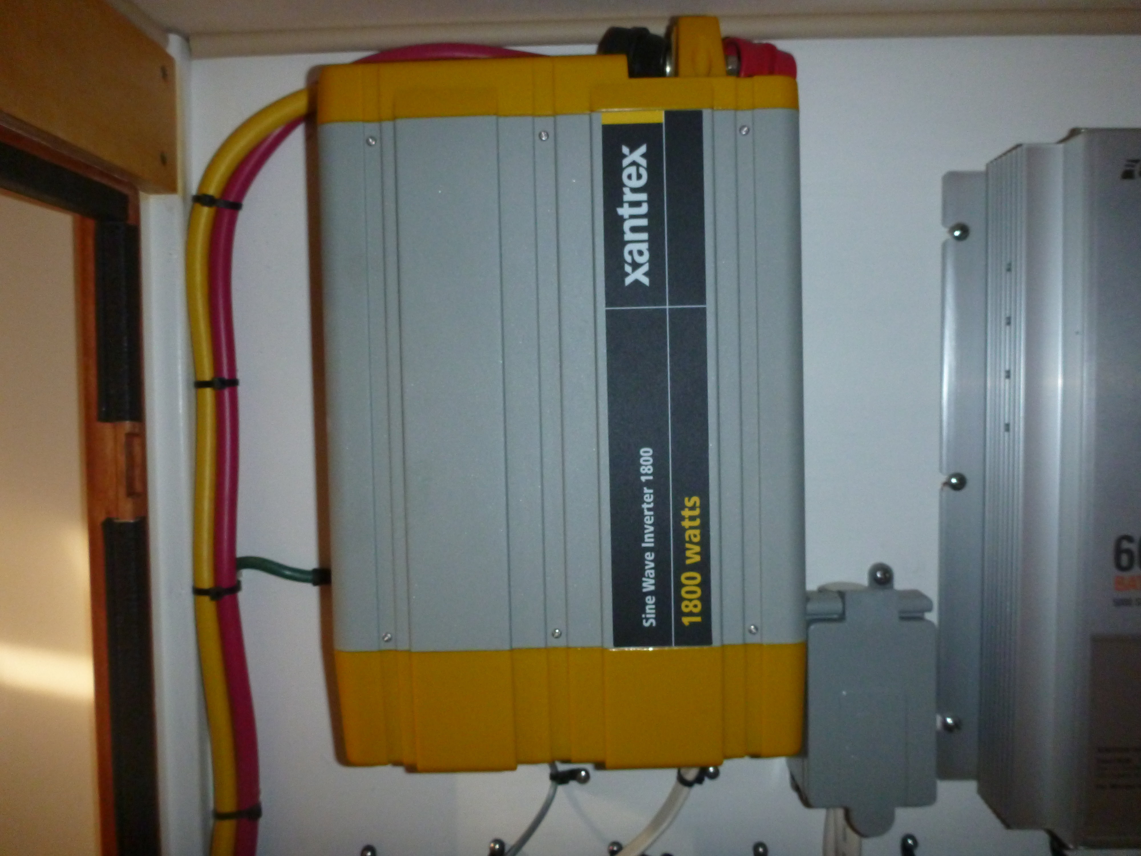
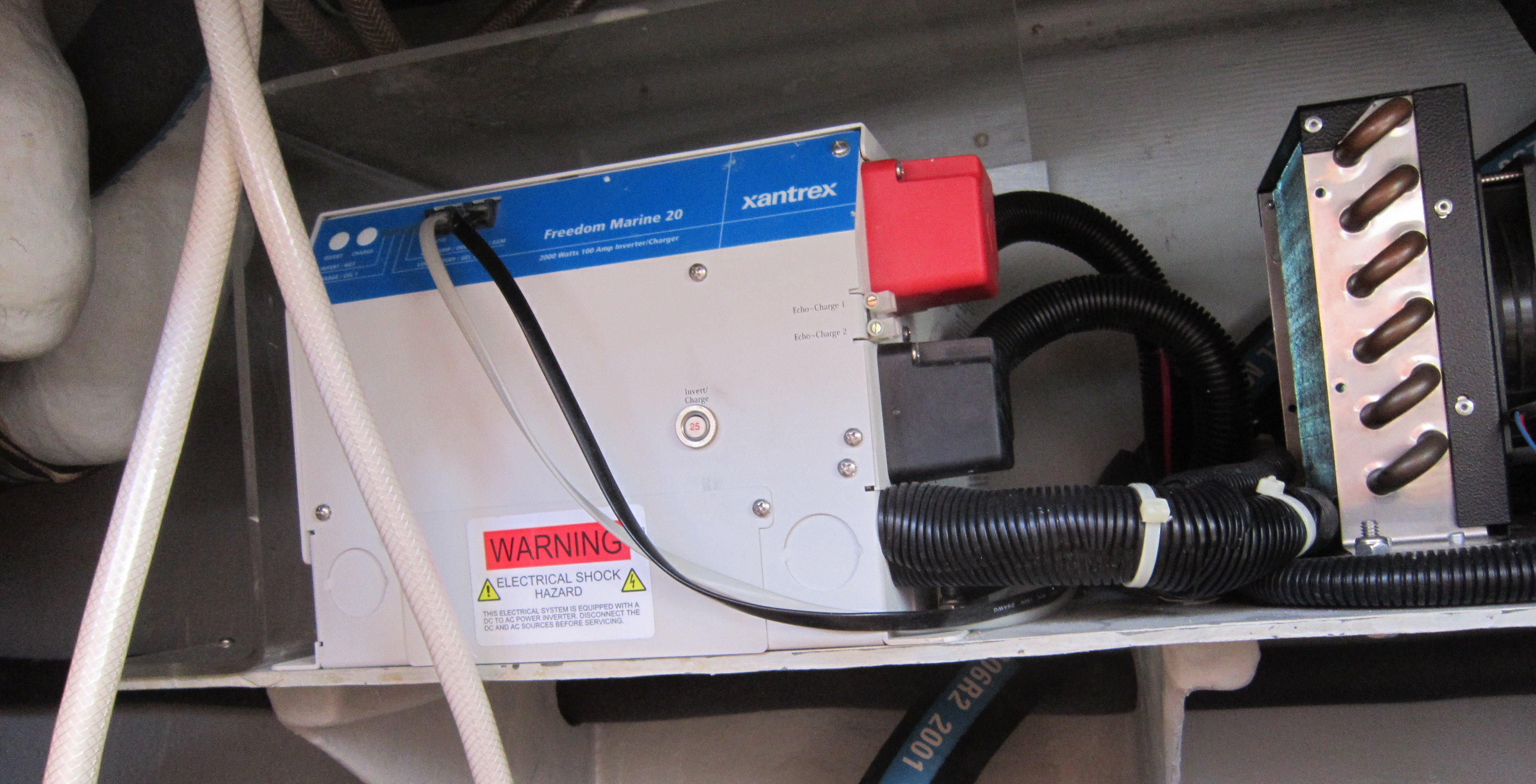 Finally consider the physical location of the inverter before installing. You want your inverter installed close to the power source to reduce the length of the conductors and possible voltage drop. The inverter should also have good ventilation to cool the unit. Many inverters produce a fair amount of heat when operating. It is of course important to make sure no water gets into or on the inverter as well. This means installing in a dry location away from water softeners or leaky plumbing, to know more about Fleck water softeners and all the way they can help, search for reviews online.
Although some of this may sound a bit complicated, it really is not if you take it one step at a time. Following these guidelines as well as the inverter manufacturer’s instructions will help ensure a safe and reliable installation. If you already have an inverter installed, it would be wise to review the installation to make sure it meets all the requirements outlined. Even if you’re only using a small portable inverter, make sure the power supply is properly fused and capable of maintaining the inverter load. A proper earth ground to the inverter case is required as well, even with small portable units. Without this you or your crew could become the path to ground, a hazard that is easily avoided.
Inverters can be a great source of quiet AC power while away from the dock but they pose the same hazards as shore side AC power if they’re not set up properly. A little care and effort with the installation will keep you and your crew safe while enjoying the benefits of quiet AC power.
If you found this helpful please like and share below to help educate others!
Capt. Wayne Canning
I came across this interesting link to a load calculator for inverters. Hopefully it will help when planning your installation. Inverter calculator
If you found this helpful please return the favor to keep the information (and rum) flowing. Please consider helping out with a bit cash. I am a cheap ass sailor and every little bit helps! Thanks!

Great article – thanks. I think I can wire my 4000 watt inverter into my distribution panel using your diagram. But, I’d feel better if you did a diagram for my 50 amp system. It’s two phase and one is dedicated to airconditioning. I plan to put the inverter on the other leg for normal plugs and such.
I have a 20 amp auto switch that I’ll use to automatically tie the inverter in when shore power or generator are off. I’ll have to watch the amps used.
I strongly recommend separating the loads for the inverter from other non inverter loads. There are safety reasons for this. A 50 amp setup is pretty much the same as the 30 if you are working with 2 legs. Make sure the neutrals are separated as well.
captain wayne
you responded to my sailing forum……….about insurance on a ferro cement boat
need more information from you
please contact me
ted manos
Hi Capt. Wayne,
I have read your understanding inverter installation just in the last week as I have just installed a new inverter/charger on my 2002 bay liner 3788, but would like to know if you have a video on the installation or additional pictures.
My main panel is identical to the wiring diagram you show with the double ac, and I also have the Generator below the main circuit breakers.
We installed a 30 amp breaker marked inverter on the right side of the panel to take the light loads such as receptacles and other small things.
On the left all the heavy loads for the generator and shore power but the shore power should run everything.
Confused about the AC in from the panel and AC out for the connections back of the panel.
Do you have a video or more pictures showing the hook up for the hot and neutral coming from the panel to the inverter and then the hook up of the hot and neutral to the panel or 30 amp breaker for the inverter, which side of the breaker would the AC hot connect to the off position or the on position. Hope that is not confusing.
Warren
Hi
Do you have any recomended inverters/installers for 3000W inverters please? I am not an electrical technician so would need lots of help doing this.
Thanks’
Pingback: 12 Volt Inverter Wiring Diagram – Schematic Wiring Diagram and Resources